
A load test is only meaningful when the test conditions are derived from an established engineering basis.
For custom lifting and rigging installations, engineering defines the intended service conditions, governing loads and how those forces are transferred through the equipment and supporting structure. Load testing provides practical verification of the completed installation against those defined conditions before certification.
Establishing the Design Basis
The first stage is to define the operating envelope of the equipment.
This includes the Working Load Limit (WLL), load direction, range of movement, attachment geometry, operating configuration and any static, dynamic or cyclic loading the equipment is expected to experience.
For an existing installation, the original design information must also be considered against its current configuration. Replacement equipment, revised attachment points, changes in geometry or modifications to the supporting structure can alter the original load case even where the nominal lifted weight remains unchanged.
Where original information is incomplete, assumptions need to be identified and substantiated before the relevant load cases and test criteria can be established.
Determining the Governing Loads
The mass of the suspended item does not, by itself, define the forces within a lifting system.
Rigging geometry can significantly alter component loading. As sling angles become shallower, tension within individual legs increases. Unequal geometry or an offset centre of gravity can produce unequal load distribution, while acceleration, deceleration and movement can introduce additional forces.
Load direction is equally important. A fitting designed primarily for axial loading can experience a substantially different stress condition when subjected to side loading, bending or eccentricity.
The engineering assessment considers the relevant load combinations and identifies the governing cases for the component, its connections and the supporting structure. These determine the required proof load and test configuration in accordance with the applicable equipment requirements, standards and, where relevant, Flag, Class or manufacturer criteria.
Assessing the Complete Load Path
The capacity of an individual component cannot be considered independently from the structure into which it is installed.
Load is transferred from the lifting arrangement through the primary component, attachment points, fasteners, welds and backing arrangements into the yacht’s supporting structure.
Localised stresses around attachment points, insufficient load distribution, misalignment, eccentricity or deformation of the supporting structure can become governing factors even where the principal lifting component has adequate capacity.
The complete load path therefore needs to be assessed for both the intended service loads and the increased loads introduced during proof testing. This is particularly important for retrofits and custom installations where the existing structure may not originally have been designed for the proposed equipment, geometry or test load.
Engineering the Test Conditions
Proof testing deliberately introduces an increased load into the system, making the test itself an engineering load case.
Its effect must be considered through the equipment, attachments and supporting structure before the test is carried out.
Test geometry and load direction must also represent the relevant service conditions as closely as practicable. Applying the correct magnitude of load in an unrepresentative direction may not verify the governing load case.
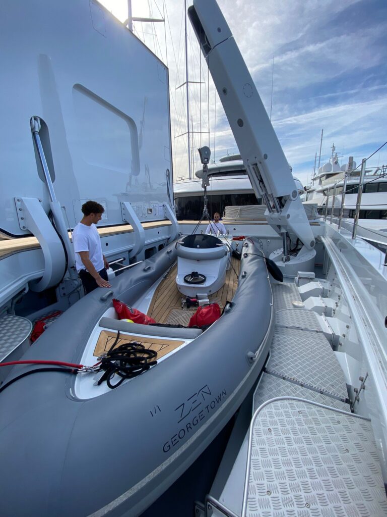
For equipment with changing geometry, a single test position may not represent the complete operating envelope. Boom angle, extension, slew position or lifting point location can alter component forces, moments and structural reactions.
The test procedure must account for these variables.
Static and Dynamic Load Testing
Static proof loading assesses the equipment and installation under a specified increased load in controlled conditions.
Operational equipment can also experience transient forces caused by acceleration, deceleration, movement or sudden changes in load. Where relevant and appropriate to the equipment, RSB can replicate shock or dynamic loading with the increased test load applied.
This allows the system to be assessed under representative operational loading rather than solely with the load suspended in a static condition.
Testing Through the Operating Range
As lifting equipment moves through its operating range, changes in geometry can alter lever arms, reaction forces, component loading, structural moments and the direction in which forces enter the supporting structure.
A crane, for example, may sustain a proof load in one configuration while another position produces the governing structural load case.
Where required, testing through the full range of movement allows the behaviour of the installation to be assessed as these conditions change under load, rather than extrapolating the result from a single static position.
Verification and Certification
Following testing, the equipment and installation are assessed against the defined acceptance criteria, including unacceptable deformation, failure or other indications that the system has not behaved as expected.
A successful test provides physical verification of the completed installation against the load cases and test conditions established by the engineering assessment.
Its scope remains defined by those conditions. Proof testing does not independently establish fatigue life, long-term cyclic performance or capacity under load directions and configurations outside the assessed test envelope.
Once the specified test procedure has been successfully completed and the acceptance criteria satisfied, the test provides the final verification step before the relevant certification is issued.
For custom and yacht-specific installations, continuity between engineering, fabrication, installation and testing ensures that the design assumptions, fabricated component, installed geometry, structural load path and final test remain technically aligned.
At RSB Rigging, these disciplines are managed within the same technical team, maintaining that continuity from the initial design basis through to final verification and certification.


