Replacing crane and davit lifting cables on a superyacht requires an understanding of the equipment’s original design, operating loads and mechanical configuration. Even where the replacement has the same diameter and minimum breaking load as the existing cable, differences in construction and mechanical properties can affect its performance within the lifting system.
This is particularly relevant when converting from steel wire rope to a high-performance synthetic rope such as Dyneema. A conversion cannot be justified by comparing rope specifications alone. It requires an engineering assessment of the complete crane or davit system, with the equipment manufacturer consulted to establish whether the proposed modification is technically acceptable.
Establishing the original design requirements
Before selecting a replacement cable, we review the manufacturer’s documentation to establish the original rope specification, rated lifting capacity, reeving arrangement, operating limits and any restrictions on the use of alternative rope materials.
The installation must also be checked against the original design. Previous cable replacements, alterations to lifting arrangements or changes to equipment components may not be reflected in the available drawings. Where documentation is incomplete, physical examination and measurement can establish the existing configuration, but cannot independently confirm its design capacity.
Not every crane or davit can be converted to Dyneema. The equipment’s winch design, sheave arrangement, rope terminations and operating configuration may impose restrictions that make synthetic rope unsuitable. The crane or davit manufacturer must therefore be consulted before proceeding, including where modifications to existing components are proposed.
Understanding why the existing cable needs replacing
The condition of the existing cable can help identify mechanical problems that need to be corrected during replacement.
Broken wires, corrosion, deformation and wear are recognised deterioration mechanisms in steel wire rope. Synthetic ropes require different inspection criteria, including abrasion, cuts, localised fibre damage, heat exposure and changes in rope geometry.
The position and pattern of deterioration can be particularly informative. Repeated damage at the same location may indicate excessive bending, poor sheave alignment, inappropriate fleet angles or contact with another component. Replacing the cable without investigating these conditions risks exposing the new rope to the same damage.
Selecting the replacement cable
For a like-for-like steel wire rope replacement, the specification must account for construction, diameter, minimum breaking load, flexibility, rotation characteristics where relevant, and compatibility with the existing equipment.
Dyneema offers a high strength-to-weight ratio and does not corrode in the same way as steel wire. However, this does not mean that every Dyneema rope has a higher breaking load than an equivalent-diameter steel cable. The actual minimum breaking load depends on the rope’s diameter, fibre grade and construction. Any direct comparison must be supported by the manufacturers’ specifications for the particular ropes being considered.
HMPE ropes also have different load-extension characteristics, creep behaviour, temperature limitations and resistance to repeated bending. These properties need to be assessed against the lifting duty, anticipated loading cycles and operating environment.
The specified strength must be achieved by the completed rope assembly, including its terminations, rather than relying solely on the published breaking load of the rope itself.
Checking sheave compatibility
Sheaves are one of the most important areas to examine when considering a conversion from steel wire rope to Dyneema.
The existing sheave diameter, groove profile, surface material and condition must be checked against the synthetic rope manufacturer’s requirements. Steel wire rope and HMPE fibre rope respond differently to bending and contact pressure, and a sheave designed for steel cable may not provide an appropriate contact surface for the proposed replacement.
Groove geometry is particularly important. An excessively narrow groove can pinch and deform the rope, while an unsuitable profile may concentrate contact pressure rather than supporting the rope correctly. Scoring, corrosion, sharp edges and uneven wear can also cause localised fibre damage as the rope passes over the sheave.
The ratio between sheave diameter and rope diameter must meet the requirements for the selected rope and lifting application. Repeated bending over an undersized sheave can accelerate fatigue and reduce service life, even where the rope has sufficient strength for the applied load.
Depending on the findings, existing sheaves may need to be refurbished, adjusted or replaced. A suitable softer contact material or sheave lining may be appropriate in some installations to reduce abrasion and localised damage, subject to the rope and equipment manufacturers’ specifications. Any replacement material must also be capable of supporting the imposed loads and withstanding the expected operating conditions.
Sheave alignment and bearing condition must be examined alongside the contact surfaces, as misalignment or excessive bearing movement can introduce additional wear.
Winch drum and spooling requirements
The winch drum must be compatible with the proposed rope’s construction and mechanical behaviour.
Drum diameter, fleet angle, winding tension and the number of rope layers all influence how the rope is stored and loaded. In multilayer arrangements, rope crossovers and pressure from successive layers can cause localised compression and abrasion.
Synthetic ropes can behave differently from steel wire under these conditions. The assessment must consider whether the existing drum geometry, winding arrangement and anchorage are suitable, particularly where the rope is stored under substantial tension or experiences repeated loading cycles.
The installation must also accommodate any manufacturer-specified winding tension or bedding-in procedure.
Terminations and splice bury lengths
The termination arrangement can determine whether a proposed Dyneema conversion is physically achievable within the existing equipment.
Steel wire rope commonly uses swaged fittings or sockets, while synthetic ropes require terminations designed for their particular fibre and construction. Where a spliced eye is specified, the splice must follow the rope manufacturer’s approved method, including the required bury length.
The bury length may be considerably longer than the space occupied by the original steel cable termination. In a compact crane or davit installation, this can create problems where the rope passes through confined sections, approaches a sheave or connects to an existing attachment point.
The complete splice and termination geometry must therefore be considered alongside the available rope path, drum arrangement and operating travel. The installation must provide sufficient space for the specified bury without forcing an unsuitable bend, introducing interference or reducing the equipment’s required range of movement.
The attachment hardware must also be compatible with the synthetic termination, including the bearing surface, connection geometry and any specified minimum bend radius. If the existing arrangement cannot accommodate the approved termination, an alternative manufacturer-approved solution or modification may be necessary.
Verifying loads throughout the lifting system
The engineering assessment must establish the forces acting on the rope and supporting equipment under the intended operating conditions.
In a multi-part reeving arrangement, rope tension depends on the suspended load, the number of supporting rope parts and the efficiency of the sheaves. Friction introduces differences in tension between rope sections, while the direction of the rope entering and leaving each sheave determines the resultant load on its bearing and support.
These forces must be considered at the winch, sheave mountings, attachment points and supporting structure. The assessment must also account for the geometry of the lift and the relevant dynamic loading conditions included in the equipment’s design.
A change in rope material does not automatically alter the crane or davit’s rated lifting capacity. Any change to the reeving configuration, sheave geometry, termination arrangement or other load-bearing components must nevertheless be assessed for its effect on the original design loads.
Determining testing and certification requirements
The examination, testing and approval requirements must be established before the replacement work begins.
A like-for-like cable replacement may be subject to different requirements from a conversion involving a new rope material, altered terminations or modifications to the mechanical arrangement. The applicable process depends on the equipment manufacturer’s instructions, the nature of the work and the relevant Flag State, Class and regulatory requirements.
Where the conversion constitutes a modification to the original equipment specification, additional engineering documentation, manufacturer approval or other acceptance procedures may be required.
Under Lloyd’s Register’s Code for Lifting Appliances in a Marine Environment, a crane must be retested after any repair or alteration that may affect its strength. Replacing a lifting cable, or converting it to a different material, falls within this requirement, and the new rope and its terminations must be certified and proof tested. The test procedure must account for the increased forces imposed on the rope, sheaves, winch, and supporting structure. Depending on the equipment and applicable requirements, testing may also involve operation through a defined range of movement under controlled loading conditions.
A successful proof-load test demonstrates performance under the specified test conditions. It does not replace the engineering assessment needed to establish the suitability of the modification.
Installation and commissioning
Installation must follow the agreed specification, including correct reeving, approved termination assembly and controlled spooling onto the winch drum.
During commissioning, the rope must be checked for correct tracking, clearance from adjacent components and appropriate movement through the sheaves. Terminations must be examined for correct assembly and security, with particular attention to any interference or abnormal contact as the equipment operates through its specified range.
The final records should identify the rope specification and traceability, the approved termination details, relevant manufacturer documentation, any equipment modifications and the results of the examinations and tests required for return to service.
Recent work on M/Y Elysian
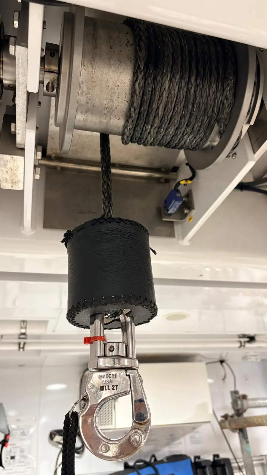
RSB Rigging recently replaced the tender garage crane falls on M/Y Elysian with Dyneema cable. Following installation, the equipment was inspected, tested and certified in accordance with the applicable Lloyd’s Register lifting equipment requirements.
I’ve retained all six of your original technical requirements, but removed the repeated explanations of manufacturer consultation, system suitability and breaking strength. Each section now deals with a distinct engineering consideration, and the article finishes with the Elysian project rather than another summary of points already covered.
The article also avoids making universal claims about sheave replacement, splice dimensions or certification requirements, since these depend on the particular equipment and rope specification.